Designing for Manufacturability: How Optic Geometry Affects Coating Success
Stress accumulation differs on thick substances, thin substrates, and freeform surfaces. There can be bending and bowing risks, coating-induced deformation, or a CTE mismatch amplified by the material curve. Curved optics are more apt to concentrate stress in one area. Thin windows are also more vulnerable to stress distribution as the material can flex.
Even when materials are correctly selected, the overlooked variable is optic geometry and how it fits into the outcome of the system performance and long-term durability.
At Omega Optical, our engineering team’s early design decisions will determine and shape:
- Coating adhesion success rate
- Anticipated stress levels of the optic in use
- Thickness, uniformity and polishing requirement of the selected substrate
- Production yield expectations for high-volume needs
What Does “Design for Manufacturability” Mean in Optical Coating?
Working towards DFM in optics (or sometimes, DFMA “design for manufacturability and assembly”) is our practice, which is a two-part approach created to decrease the cost of a project. The core principles are design, looking at the number of optics or components required in the system, and then streamlining that process for optimization throughout the production phase.
Omega Optical optical coating engineers evaluate:
- Shape of the material and final optic
- Aspect ratio and thickness of coated material
- Edge conditions – beveled, housed
- Mounting method of the optic into the final system
One of the elements that is frequently behind the scenes, but greatly impacts the outcome, is the selected deposition method (PVD, sputtering, PE-CVD) and how each responds differently to geometry. No coating chamber is designed to coat every possible material size and shape, or every specific coating requirement. Omega utilizes multiple types of coating chambers from PARMS, Ion-assisted, E-beam, and PVD, all for specific selected coating results for a wide range of material geometries.
How Optic Geometry Influences Coating Uniformity
Flat Optics vs. Curved Optics
Required thickness gradients on convex/concave surfaces can pose questions for coating engineers. Angular deposition has a strong effect on different-shaped optics, and our IR optic facilities in Ayers and Hopewell Junction can accommodate it and plan accordingly. Each site is equipped to handle either flat or curved IR optics with exceptional accuracy.
Rotational fixture considerations come into play with the selected tooling, size of the blank parts and the length and complexity of the required coating on either a flat window or complex curved optic.
Large-Diameter Optics
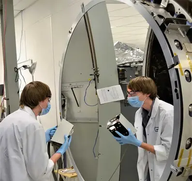
More surface means more surface to control. Omega Optical is known for our ability to safely handle and coat a single part up to 40” diameter in our Ithaca facility. Whether one window or mirror is needed, or multiples at incredibly high volumes (if small optics are required), our expert team will design for glass, ceramic, composite, plastics and metals.
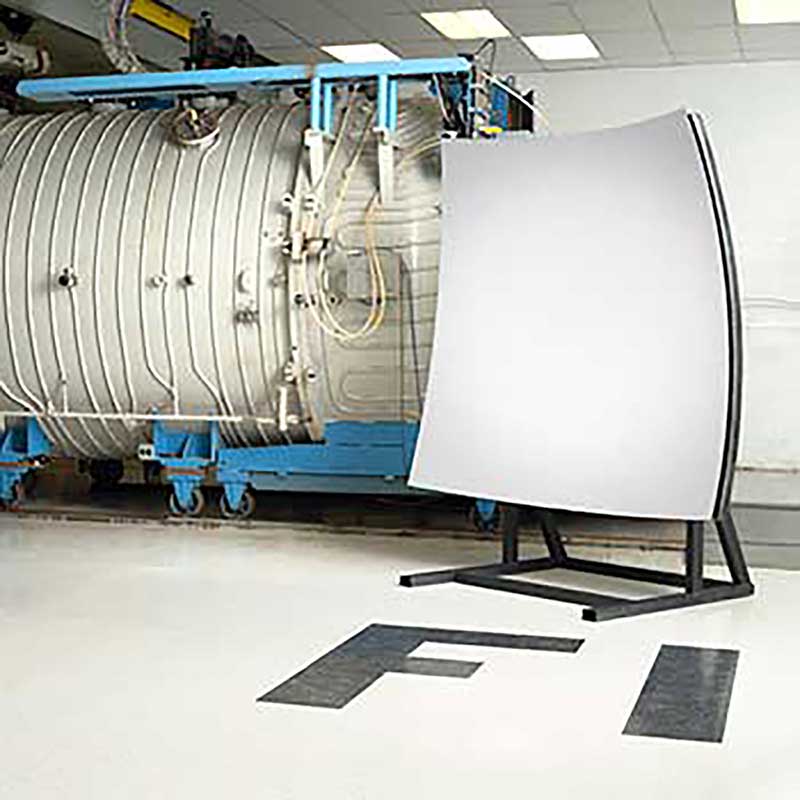
Not only is the geometry important for success in these cases, but the total weight and thickness of the material also come into play when coating a large optic. Stress behaviors, thermal response of the substrate, uniformity controls and yield risks are all discussed and fully evaluated before any production occurs. A coating chamber needs to withstand vacuum forces, handle temperature ramping to high temperatures, and accommodate spinning or tilting of the inner fixture. All of these forces are amplified when talking about large-scale optics.
Parts need to rotate fully, and if the fixture is too heavy, there is a risk of coating deflection. If the optic is too thin to coat at the requested dimensions, flexing may occur, causing poor adhesion or uniformity concerns.
- Thickness controls require nanometer accuracy, so structural sag matters here.
- Planetary rotation requirements – Geometry related to the coating cloud, optic shape, weight and requirements for uniformity to ensure consistent coating.
- Tooling design is handled by using either custom-made parts or our tooling library
- Another key ability is safely handling and shipping large parts up to 5,000 lbs
- Understanding of thermal mass and heating, as large optics heat and cool down more slowly, which may cause temperature gradients across the material.
- Avoiding spectral shift due to thickness variation
Surface Finish and Geometry Interaction – How this plays into high-volume manufacturing
- Micro-roughness impact on adhesion
- Polishing quality at edges
- Geometry-driven cleaning challenges
- Contaminant traps in complex shapes
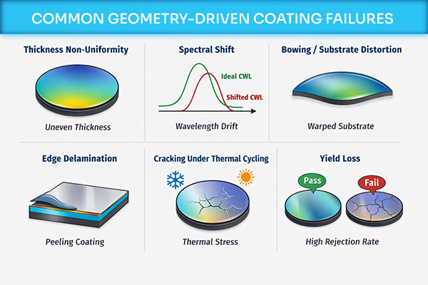
Common Geometry-Driven Coating Failures
Best Practices for Designing Optics for Coating Success
Maintain realistic aspect ratios |
Avoid unnecessarily sharp edges |
Match substrate thickness to coating stress |
Account for fixturing orientation |
Engage coating engineers early |
Understand chamber size constraints |
When You Should Consult an Omega Optical Coating Engineer?
Get ahead of any and all foreseeable manufacturing problems by collaborating early with technical experts. With over 85+ years of optical coating excellence, our team knows how to reduce or eliminate problematic redesign cycles, find ways to improve cycle yields to hold costs down and remove surprises when going to market.
Omega is your technical partner. Our expertise runs deep, as does our enthusiasm for problem-solving.
Design decisions made at the beginning of a project will affect the performance, durability and production scalability and can make or break the outcome and financial success of your optical system project.
Proactively collaborating with partners who deeply understand your technology, its requirements, and how to best apply the right approach for optical coating success.
Designing a new optical system? An early coating review can prevent costly redesigns later.
Speak with an optical coatings engineer about your system requirements today.


